
Before starting let's make an initial disclaimer:
Are you still here? Great, let's go!- This is an amateur program made on my free time. Don't expect anything near perfection.
- I made it because I like to learn I'm curious and I'm slightly mad ;).
- There are bugs!
- If your PC explodes, burns or anything crazy, I wont assume responsibility. Use at your own risk.
- There are no virus in the files, but please test everything before using and let me know of any problem.
- Interface could be better.
- Before you say it, let me say that this is a "@?!#$%!" program. Now you don't have to say this.
- If you think what I say in the above line, just don't install and don't use it. You are making yourself a favour, not to me.
- If you like it and want to use it and you have some money to spare and think I deserve for my work and want me to upgrade the software, you can make a donation. I will be really thankful.
- This is not laser scanning, there are many errors and imprecisions, some of the methods used are guessing or interpolating values, so you can get some crazy results.
- Follow my indications. That's how I made my test's and got results. You might find better methods to work with the program. If you find them, just share.
INDEX
Requirements
Installing PVS
I want to see 3D reconstruction right now!
Program components
PVS interface
Project
Cameras
Capture
Calibration
Reconstruction
Correction
REQUIREMENTS BEFORE INSTALLING PVS
Well I tested PVS on 4 PC's and it worked well, they where Windows 7 and 8 64 bits, with more than 4GB memory. If you have a similar system it should work. If you have problems, just share so I can try to solve them or for others to know the minimum requirements (Windows Vista or less is not compatible).
PVS requires the installation of two video codecs, Xvid and/or Huffyuv.
Xvid is required if you want to test the sample video that comes with the program.
Please take a look at the codec installation page where I have the why and how about the codecs.
INSTALING PVS
Got the download? If not go to the download page.
Now unzip the compressed folder to your preferred location.
Create a shortcut from PVS.exe on your desktop or start menu.
Run the program from the shortcut.
You might see an initial screen:

If not, let me run before you start complaining.
If yes congratulations! You are running PVS Yehh!
I WANT TO SEE 3D RECONSTRUCTION RIGHT NOW!
Ok ok.... The file you downloaded contains a sample project.
Just go to File -> Open Project.
Next open the folder: "Your location/PVS/Sample Project" and select "Sample Project.yml"
Now go to the Reconstruction tab and press "Start reconstruction".
Just contemplate... If you want to understand all of this, make your scans and open the point clouds, keep reading!
PROGRAM COMPONENTS
Well PVS is composed by 5 modules:
- Colours.exe - To adjust camera setting.
- Capture.exe - To capture 3D movies from two webcams.
- Calibration.exe - To calibrate your rig and cameras
- Reconstruction.exe - To create point clouds from calibrated stereo movies.
- Correction.exe - To correct angles and translations in the point clouds.
The script contains all the settings and configurations needed for each of the modules.
Since it was a bit complicated to work directly on the script and I'm not detecting all possible errors on the script I decided to create an interface to generate the script and run the modules.
That interface is PVS.exe.
PVS INTERFACE
Here we create the script (project) that we feed to the modules. We can also call the modules from this interface.
Let's talk about the tabs:
STEP 1 - Project

Here is indicated the name of the project and its folder.
You can load or create a new project from the top menu, just select File->New project or File->Open project.
The project name is used to create the project folder and the project file inside that folder.
When you create a new project PVS creates a tree of folders:
Sample Project (folder with the project name)
Sample project.yml (the project script file with the project name)
Captures
Road0.avi (captured video files)
Road0.txt (frame capture times)
Road1.avi
Road1.txt
Calibration0.avi
Calibration0.txt
Reconstructions
DRoad.yml (camera dislocations file)
Relative
RRoad0.ply (relative point clouds)
RRoad10.ply
RRoad20.ply
Absolute
ARoad0.ply (absolute point clouds)
ARoad10.ply
ARoad20.ply
Corrected
CRoad0.ply (corrected point clouds)
CRoad10.ply
CRoad20.ply
The folders will be empty when you create the project.
Basically you should create at least one project for each camera rig and calibration.
The idea is to create a rig, calibrate the rig and use the rig for multiple scans.
So you might use the same base project for many scans. If you want to use a different resolution, you must make a new calibration. Just create a new project.
STEP 2 - Cameras
Before capturing we need to configure our cameras.
Selected options can seriously affect capture performance.
When connecting the cameras pay attention to the following:

Left camera/Right camera
Select the cameras you want to use.
If you connected the cameras after starting the PVS, click the "Update cameras list" button. Now you should see the cameras in the list.
It's not important to select the right cameras for left and right. You can switch them in the Colours module.
When you select the cameras, PVS stores the camera index in the script. That camera index might not be the same on another computer so if you use the project script on another computer, the cameras might be swapped, but it only affects the colours and capture module.
Resolution
Here you select the pretended resolution.
The list shows only the matching resolutions between both cameras.
640x480 is a good resolution. Most cameras are pretty fast at this resolution.
If you have a camera with 16:9, use a resolution like 864x480 to get the most horizontal information possible.
Don't forget that using HD or even FullHD on USB devices can become problematic for obtaining synchronized frames since you are requiring more bandwidth.
Run cameras settings adjustment buttonBasically you should create at least one project for each camera rig and calibration.
The idea is to create a rig, calibrate the rig and use the rig for multiple scans.
So you might use the same base project for many scans. If you want to use a different resolution, you must make a new calibration. Just create a new project.
STEP 2 - Cameras
Before capturing we need to configure our cameras.
Selected options can seriously affect capture performance.
When connecting the cameras pay attention to the following:
- Bandwidth, bandwidth, bandwidth, bandwidth, bandwidth.....
- Your PC might have USB1.0, USB2.0 and USB3.0. Connect the cameras to the fastest ports available.
- Today most of consumer cameras are USB2.0, so use those ports, not USB1.0.
- Using USB3.0 on USB2.0 cameras as been a problem for me, but maybe not for you.
- If you have independent ports, use them. Shared ports reduce your bandwidth. Strangely on my laptop I get better results sharing the same port!?.
- Disconnect other USB peripherals that might stole bandwidth.
- If you have to use cable extensions, use the smallest ones possible.
- Close unnecessary applications.
Left camera/Right camera
Select the cameras you want to use.
If you connected the cameras after starting the PVS, click the "Update cameras list" button. Now you should see the cameras in the list.
It's not important to select the right cameras for left and right. You can switch them in the Colours module.
When you select the cameras, PVS stores the camera index in the script. That camera index might not be the same on another computer so if you use the project script on another computer, the cameras might be swapped, but it only affects the colours and capture module.
Resolution
Here you select the pretended resolution.
The list shows only the matching resolutions between both cameras.
640x480 is a good resolution. Most cameras are pretty fast at this resolution.
If you have a camera with 16:9, use a resolution like 864x480 to get the most horizontal information possible.
Don't forget that using HD or even FullHD on USB devices can become problematic for obtaining synchronized frames since you are requiring more bandwidth.
Clicking this button starts the colours module.
The colours module or cameras settings
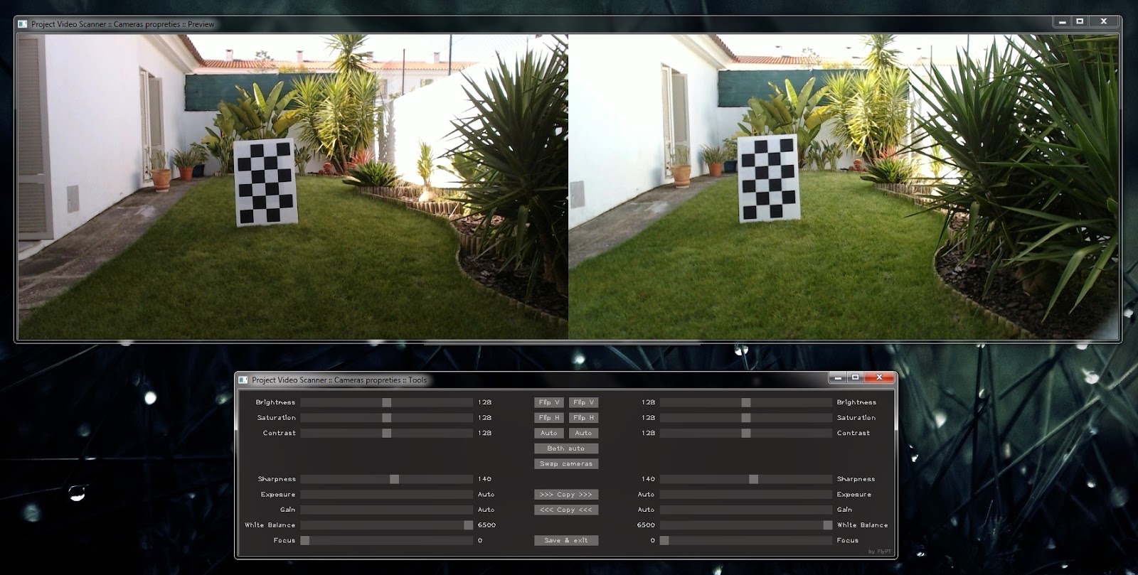
It's composed by two windows, one with the cameras capture and another with the tools.
Use the controls to adjust your cameras.
Some controls might be hidden. If your camera has no autofocus it will not be shown.
Try to match colours between both cameras and flip or switch cameras as necessary. I have mine mounted on the rig upside down, so I flipped them horizontally.
When terminated, press the "Save & exit" button and your configurations are stored in the project file.
If you don't want to save, close one of the windows and the module ends execution.
From my experience, try to adjust the cameras so you get a good definition. Use sharpness for that, but not to much.
Focus, and white balance should not be in auto mode. If focus changes, your calibration wont be valid any more. My focus is at infinity.
Exposure and gain should be left in auto mode. You can fix them but when you enter shadows or lighted ambient not having automatic compensation might bring problems.
In auto mode you might obtain colour variation between frames when you go from shadow to light, but that's tolerable unless you want perfect colours match in the point cloud.
STEP 3 - Capture
To make the point clouds you need to capture a 3D movie.
To calibrate your cameras/rig you also need to capture a 3D movie of your calibration pattern (calibration is the next step).
So here's the section dedicated to capture movies.

Capture folder
Folder where the captures will be saved.
By default, on project creation, the folder is the "name of project/Captures".
Base file name
The captures will be saved with this name appended with a number.
There's a 4GB limit on file size, so when we reach that size, the file number is incremented.
This occurs specially if you are using lossless codecs with low compression.
Allow overwrite
Check if you allow previous movies with the same name to be replaced by the new ones.
Frames skipped
When recording video you can specify the number of skipped frames before saving another one.
If you have high capture rates and want to save some space you can save only 1 frame in 5 captured frames. For that you must specify 4. Keep 0 to save all captured frames.
How to install the Xvid/Huffyuv codecs
You will be directed to the codec page in this blog.
Run capture
Press the button to start the capture module.
The capture module
The capture module, captures frames from two webcams, the fastest way I was able to do.
It has to be fast if we are capturing while we are moving. If the cameras are not synched there will be differences between frames and errors in the reconstruction.
You can also take snapshots. If you are not able to make a synced movie for hardware reasons, you can put the rig in stand still and make a snapshot then change the camera position and make another snapshot and so on. There wont be any problem of synch that way.
The capture doesn't save audio and doesn't synchronize the movie, frames are saved at 30fps but they are captured the fastest way possible and that might be a different value from 30fps.

Once more you have two windows in the capture module.
A preview of the capture and a tools window with the capture controls:
Record
Press to start/stop video capture.
Take Photo
Press to take a snapshot. You are adding one frame to the movie.
The control is disabled when you are recording video
Enable Filter, track bar and green/red square
You can use a filter to filter what is "supposedly" bad synchronized frames.
While capturing I count the time elapsed between the end of capturing in one camera and the end of capturing from the other camera. This is not a real value, since the webcams might capture simultaneously, but the processing time to acquire the frames might introduce some lag even if the cameras are synchronized.
A big time can be for many reasons, but also because of bad synchronization between cameras.
So if you want you can specify a value (in milliseconds) and record only the frames with a time under that value.
Red square are times above the specified, green under.
My recommendation is to ignore this, since the capture times are recorded on a separate file (with the same name of the video file) and you can filter the frames on the reconstruction step.
From my experience, I was able to capture 864x480 px frames in synch up to 70km/h.
Lower speeds could only enhance the capture quality. Just be careful driving and look for others on the road.
Avoid sudden movements, especially if you are making the movie with the rig in you hand or bike.
Everything should be smooth, no tight turns, up and downs and vibrations.
Just test yourself, there's nothing like some experience and patience.
Capturing video for calibration
Visit the calibration page in this blog to make the calibration template and look at step 4 for more info about the calibration.
To make the cameras/rig calibration we have to make a movie of the calibration pattern.
From my experience, I recommend that you put the calibration pattern vertically in stand still and move your rig in such way that you make a movie of the pattern where she goes through all the image in both cameras.
Make slow movements.
Rotate the pattern and repeat, capturing the pattern in all the surface of the frames.
Repeat for different depths.
For reference, look at the calibration movie in the sample project.
STEP 4 - Calibration

Here we are, one of the most important aspects (if not the most) to get a good reconstruction.
The cameras/rig calibration is made using one captured movie of the calibration pattern.
On this step you choose the movie and make the calibration.
You can also generate your calibration pattern. For more info about this visit the page calibration on this blog.
Calibration video
The video you captured of the calibration pattern
Run calibration button
To start the calibration module.
Width, height and square size
Those are the pattern dimensions. You can see the generated pattern on the right of the window.
Save pattern bitmap (150 dpi) button
If you press this button, PVS will generate a 150 dpi bitmap of the specified calibration pattern.
Build your calibration pattern
You will be redirected to the page calibration on this blog.
The Calibration module
Interface while capturing template:

Hide stripes
there are shadowed stripes in the image. I use them to test calibration results. Here you can test the rig for alignment before calibrating.
Notice the bottom of the pattern badly aligned on both images.
Load calibration
If you already have a calibration done, load the results just for testing.
On the sample project, the calibration is done, you can load the calibration for testing.
Left/Right, Stereo and All
Captures the pattern only on the selected camera.
Stereo captures the pattern if she's found on both images.
All, captures as Left, Right and Stereo.
The number of captures in each case is shown in the button.
Full calibration/Stereo calibration
This performs the calibration after capturing the pattern.
The buttons are enabled only if you have captured at least 4 times the pattern.
Stereo calibration uses the patterns detected with Stereo.
Full calibration calibrates first the cameras and then the rig, so it uses for the cameras, Left and Right captures (there are positions on the camera that are not visible for the other camera) and for the rig the Stereo captures.
The difference between both is the captures used for camera calibration (to get undistorted images).
Interface while testing calibration results:

After the calibration you can test the results.
The two images should be horizontally aligned. Features in left should be at the same height in the right.
Use the slider to change frame and test all the movie.
You now have access to the following buttons:
Show/Hide disparity
You can test the calibration enabling the depth map. The above image has acceptable results.
Enable/Disable Histogram Normalization
If you have bad disparity results, you can try enabling this to see if it enhances features detection.
It's good to notice video compression if you are using Xvid.
STEP 5 - Reconstruction

This is the main step of PVS. That's where we create the point clouds.
Let's explain the options:
Video file
The video we want to reconstruct.
From frame x to y step z
Witch frames are we going to reconstruct.
Step depends on the captured frames. If you used snapshots, use 1 as step to go by all frames.
If you used video recording, you probably can use a value from 4 to 10.
All depends on the car speed when capturing and on the quality/range of reconstruction pretended.
If you use a big step, you will loose connection between frames and it will be impossible to get the camera motion. Be careful selecting this value (test).
Manual reconstruction
If you want, instead of automatically selecting the frame, you can use a manual selection of the reconstructed frames on the reconstruction module.
This is useful if you have badly synchronized movies. This way you can select the frames manually, using only the good ones.
Maximum frame time
Remember the filter in the capture module? If you didn't use the filter, you can filter now.
In auto mode you can filter frames captured above a determined time (milliseconds).
If the time is above this value, the reconstruction module goes to the next frame.
To ignore this, use a large value like 100 or erase the file with the times for this video.
I don't use the filter because my captures are normally synchronized but if you have problems maybe this filter can help you.
Scale
Scale applied to the video frame.
If you use 0.5 you are rebuilding only half of the points at half the scale. The point cloud will be half scale also.
Bad calibration and synchronization can be masked by scaling down the image. But that will be bad practise.
Smooth
The same as above, smooth the image to mask bad calibration and synchronization.
Histogram normalization
Might enhance disparity maps. For me this is not working. If the features don't exist in the frame we can not create them... Maybe we can... could be an idea to enhance the program.
Cut top/bottom
If you have to much sky or you see the car bonnet, you can cut them out of the image.
Car bonnet or any other stationary item should not be visible.
Cut white/black
Usually I don't use cut black, but since I added the white, why not the black.
When we make the disparity map, he is made with grey scale images (0 to 255).
Normally the sky is white, but with clouds and gradients it might insert errors on the disparity. One way of clearing the sky is saying to put all white above 200 with the 200 value. Understand?
Use the value you think is appropriate. It's not always necessary but might help. Sometimes with trees we get sky reconstructed and using the cut white helps reducing those errors.
Cut black might be used for shadows. Just try.
Adaptive disparity
Try on/off and see the differences.
This enables interpolation between depth layers.
If you disable this you will understand why far points have bad precision and near ones can be really accurate.
Median disparity
Keep disabled. It introduces some errors on the disparity. just for tests.
Gap fill
When we calculate the disparity map there are always holes.
You can fill them by interpolation, but you are guessing.
Insert the value until where you want to fill. Zero is disabled.
Module options
Unfortunately I had many problems with the 3D viewer in one of my PC's.
He couldn't handle large point clouds. I tried everything but no solution was found so if you have problems you can disable the viewer or reduce the number of points shown during reconstruction.
"Recons." his the number of reconstructed points and "Camera" the cameras position points.
If you disable the viewer, since the point clouds are created by frame, you can open them in the ".../Reconstruction/Absolute" folder with Cloud Compare or MeshLab as they are created and visualize the results.
Sorry about that, but to solve this I will have to make a viewer from scratch.
Reconstruct left/right
Check witch images to reconstruct. Both will give double density on the point cloud.
Step horizontal/vertical
Use 1 to reconstruct all points or another value to skip some points reducing point cloud size making some kind of sub sampling.
Disparity from/to
Disparity is the horizontal difference between a feature in left image and the same feature in the right image.
So a value of 0 is for distant features/object a value of 255 for close objects.
You can filter the reconstructed points. Remember that far points have much more errors.
Avoid 0.
Maximum/Minimum XYZ
This defines a box around the camera in meters.
Only the points inside this box will be reconstructed.
X=Left to right.
Y=Top to bottom.
Z=Depth.
Distance centre/Overlap factor
You can associate the reconstruction points to the camera dislocation between frames.
If the dislocation is 5 meters, PVS will reconstruct that distance multiplied by the overlap factor.
That distance is reconstructed around a centre point.
For example you set the distance centre to 8 meters with an overlap of 2. For 5 meters dislocation, PVS will reconstruct points between 8-(2*5)/2=-2 meters of the camera to 8+(2*5)/2=13 meters of the camera.
Point Cloud Treatment
You can apply some filters to the generated point cloud (by frame).
To apply filters to all the point cloud, use a third party program like Cloud Compare or Meshlab. Just drop all frames point clouds inside to open them all and treat them as one.
Radius outlier removal
With this you can remove isolated points from the point cloud.
You define a radius (meters) and inside that radius how many points we should have to keep the centre point.
Voxel grid downsample
Imagine a grid with the x, y and z dimensions (meters), now all points inside the delimited volumes are analysed and converted to only one point, not in the centre of the volume but on the centre of "gravity" from the points inside the volume.
Output results
Select what you want to generate.
You might only need camera dislocation.
Run reconstruction button
This will start the reconstruction module.
The reconstructed points are now defined by the intersection of all the filters specified on this step.
Now let's look at the reconstruction module.
Reconstruction module - Manual mode
You are in this mode if you selected manual reconstruction.

This module is composed by two or three windows:
3D preview that you can disable on the interface.
Preview window where you can test the frame for synchronism an see the feature match and disparity results.
Tools window to control the reconstruction.
3D viewer controls
To control the viewer, use the following controls:
Here you can visualize the frame being treated.
On top we have the corrected frames in colour.
On the middle the features used for camera dislocation calculation.
Green ones are good features, yellow a bit worst and red are bad ones. This is determined by height difference between left and right images.
The program ignores bad features automatically.
On the bottom we have the disparity map. If we generate left and right point clouds we will see both disparity maps.
Frame
Select here the frame you want to reconstruct.
If you chose frames that are to far one from the other, the camera dislocation will fail so be carefull choosing the frames sequence.
3D
To create point cloud for the selected frame
Show/Hide stripes
Has the name says, you can hide the alignment test stripes.
I use them to test if the left and right frames are synchronized. Features should be at the same level.
Enable/Disable histogram normalization
Might enhance features detection and depth map generation.
Hide/Show disparity
Hiding disparity makes frame change faster. Disparity will be calculated and shown when you press the 3D button to generate the point cloud.
Exit
To exit the program and end the reconstruction.
To control the viewer, use the following controls:
<+> and <-> to change points size.Preview window
<F> to select centre point.
<R> to reset the camera (see all reconstruction).
Mouse left click + mouse move to rotate view around centre point.
Mouse right click + mouse move to zoom in and out.
<Shift> + mouse move to go up and down.
<Ctrl> + mouse move to rotate.
<M> show/hide reconstruction points (only camera dislocation).
Here you can visualize the frame being treated.
On top we have the corrected frames in colour.
On the middle the features used for camera dislocation calculation.
Green ones are good features, yellow a bit worst and red are bad ones. This is determined by height difference between left and right images.
The program ignores bad features automatically.
On the bottom we have the disparity map. If we generate left and right point clouds we will see both disparity maps.
Frame
Select here the frame you want to reconstruct.
If you chose frames that are to far one from the other, the camera dislocation will fail so be carefull choosing the frames sequence.
3D
To create point cloud for the selected frame
Show/Hide stripes
Has the name says, you can hide the alignment test stripes.
I use them to test if the left and right frames are synchronized. Features should be at the same level.
Enable/Disable histogram normalization
Might enhance features detection and depth map generation.
Hide/Show disparity
Hiding disparity makes frame change faster. Disparity will be calculated and shown when you press the 3D button to generate the point cloud.
Exit
To exit the program and end the reconstruction.
Reconstruction module - Automatic mode
You are in this mode if you didn't select manual reconstruction.
It's similar to the manual one but with different controls.

Follow/Free
If you have the 3D viewer enabled, you can move the camera with the mouse selecting the free mode or make the camera follow the reconstruction with Follow.
Pause/Continue
To pause the reconstruction
Exit
To exit the program and end the reconstruction.
You may need to wait since when you make the program end, the current frame as to be completely treated and the cameras dislocation file closed.
There are other controls (this viewer comes from the PCL - Point cloud library).
The viewer from the correction module uses the same controls.
STEP 6 - Correction

Correction step is necessary because there are always errors on reconstruction.
You can reduce the errors making a good calibration and good captures (image quality and synchronization) but even so there will be errors.
Here you can correct the camera dislocation, adjusting this way the created point clouds.
Poses file to correct
That's the file with camera position information.
She was generated when you made the reconstruction.
You will find the file inside the Reconstructions folder with a name like "DName.ply".
Load existing correction
If you have make any correction previously, check this box to load that correction.
If unchecked the module will load the original cameras position.
Run correction
This will start the correction module.
The correction module

The correction module has 3 windows.
A 3D viewer, a movie viewer and the tools window.
3D viewer
Here we can see the original (faded) and the corrected camera dislocations.
There's a rectangle indicating the selected frame on both dislocations.
Remember that the dislocation represented is the cameras dislocation, not the road profile.
You can control the 3D viewer with the controls mentioned in the reconstruction module.
Movie viewer
Movie viewer
This one shows the currently select frame (left camera).
Over the image we have 3 indicators wit the angles of the camera on that frame.
Tools window
You have multiple controls to adjust the camera direction and translation.
We can change 6 parameters. 3 for direction and 3 for position.
First you should correct rotations (direction/pose) of the camera.
Only after the rotations correction concluded you should if needed correct translations.
Normally angles correction should be enough.
The program corrects always the angles first and only after that is applied the translation correction.
For a determined frame it's possible to fix one or more of those parameters so they don't change for that frame when you change on another frame.
Remember again that fixing x translation will fix x translation when you make translations, but not if you change angles. Only the delta x will be stored and preserved but x will change value if you change the angles.
Frame
To select the frame we want to correct.
X/V
X/V
On the left we have 6 buttons. They show/hide the chart of the corresponding colour.
Roll/Yaw/Pitch
To change angles of the camera in degrees where:
Roll is the rotation around the z axis.
Yaw is the rotation around the y axis.
Pitch is the rotation around the x axis.
Latitude/Longitude/Elevation
To change translation of the camera in meters where:
Latitude is the translation in the z axis.
Longitude is the translation in the x axis.
Elevation is the translation in the y axis.
I'm sorry, but for now those parameters can't be corrected with GPS units. This will come in a future version.
Fix/Unfix buttons
Here you fix/unfix one of the 6 parameters.
The fixed frames are marked in the chart.
Reset Rotations/Translations
To reset the values to the original ones.
Save corrections
Saves the corrections on the dislocation file but doesn't calculate the new point clouds
Correct cloud
Corrects the absolute point cloud. Create a new corrected point cloud for each frame in the corrected folder.
It also saves the corrections on the dislocation file.
Chart
Represents each of the 6 properties scaled to fit the available area.
Faded are the original values.
Use the X/V buttons to show/hide some of the charts.
Exit
To terminate the module.
SCRIPT
This is the generated project script.
Take a look if you are curious.
Might help solving some bugs in the future.

Ok, that's all.
Good luck in your captures!
Share your experience and feel free to make any question or suggest modifications.
Pedro Antunes
Sorry for my English errors!
Roll/Yaw/Pitch
To change angles of the camera in degrees where:
Roll is the rotation around the z axis.
Yaw is the rotation around the y axis.
Pitch is the rotation around the x axis.
Latitude/Longitude/Elevation
To change translation of the camera in meters where:
Latitude is the translation in the z axis.
Longitude is the translation in the x axis.
Elevation is the translation in the y axis.
I'm sorry, but for now those parameters can't be corrected with GPS units. This will come in a future version.
Fix/Unfix buttons
Here you fix/unfix one of the 6 parameters.
The fixed frames are marked in the chart.
Reset Rotations/Translations
To reset the values to the original ones.
Save corrections
Saves the corrections on the dislocation file but doesn't calculate the new point clouds
Correct cloud
Corrects the absolute point cloud. Create a new corrected point cloud for each frame in the corrected folder.
It also saves the corrections on the dislocation file.
Chart
Represents each of the 6 properties scaled to fit the available area.
Faded are the original values.
Use the X/V buttons to show/hide some of the charts.
Exit
To terminate the module.
SCRIPT
This is the generated project script.
Take a look if you are curious.
Might help solving some bugs in the future.
Ok, that's all.
Good luck in your captures!
Share your experience and feel free to make any question or suggest modifications.
Pedro Antunes
Sorry for my English errors!